
Types of systems
Membranes
Solution for complicated projects

Membranes: Solution for complicated projects.
In practice, we often encounter systems that use a single diffuser for both cooling and heating. This approach suits most applications; however, there are physical limitations that can significantly affect efficiency—especially when the system needs to provide both heating and cooling.
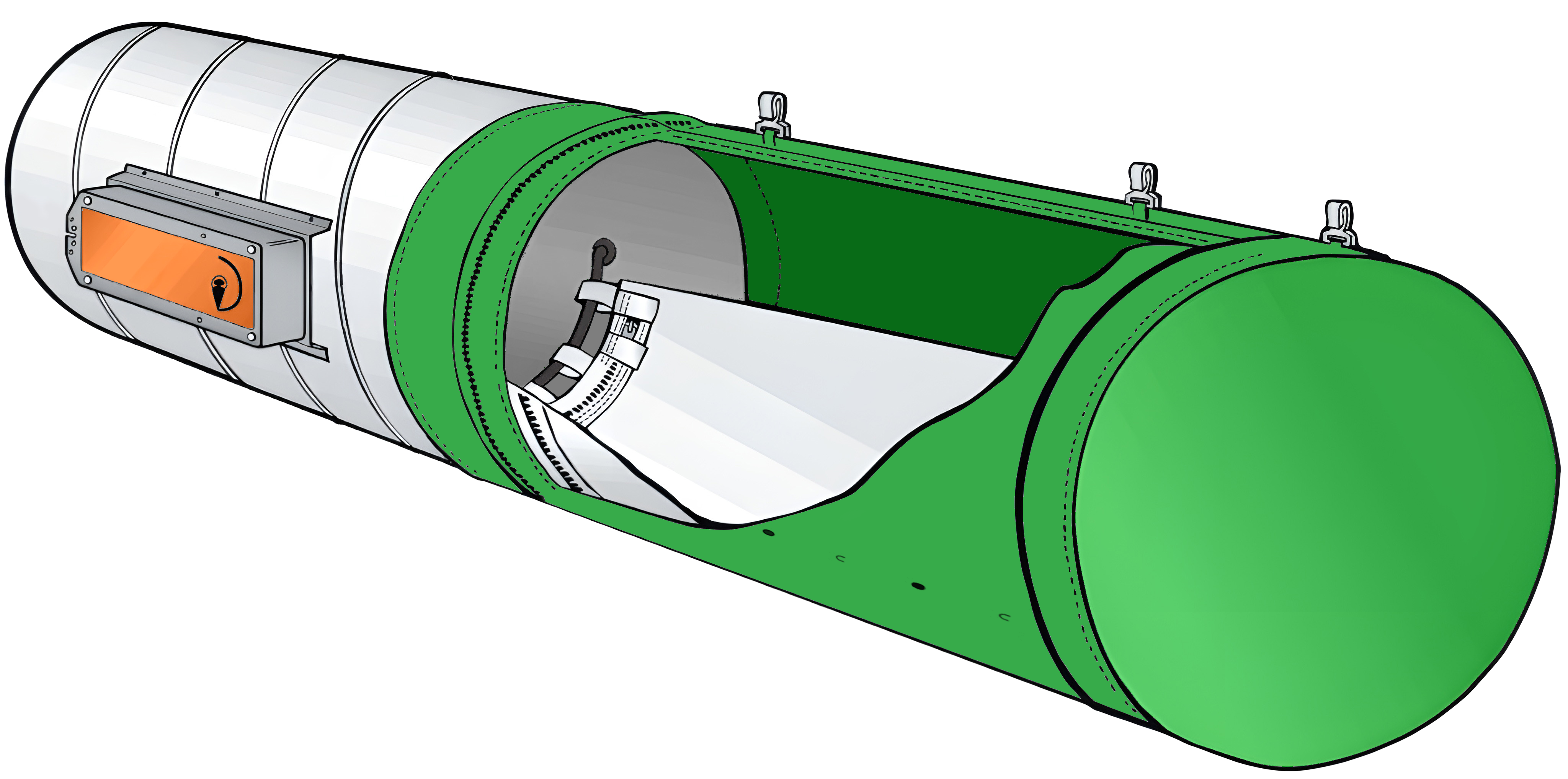
Principle of the membrane system
The main issue lies in the different physical properties of cold and warm air. Cold air has a higher density and therefore naturally sinks. Warm air, due to its lower density, rises. The membrane offers an effective solution by integrating both cooling and heating systems into a single textile outlet. Each half of the duct is designated either for cooling or heating, separated by an airtight layer that switches between the two systems based on current needs.
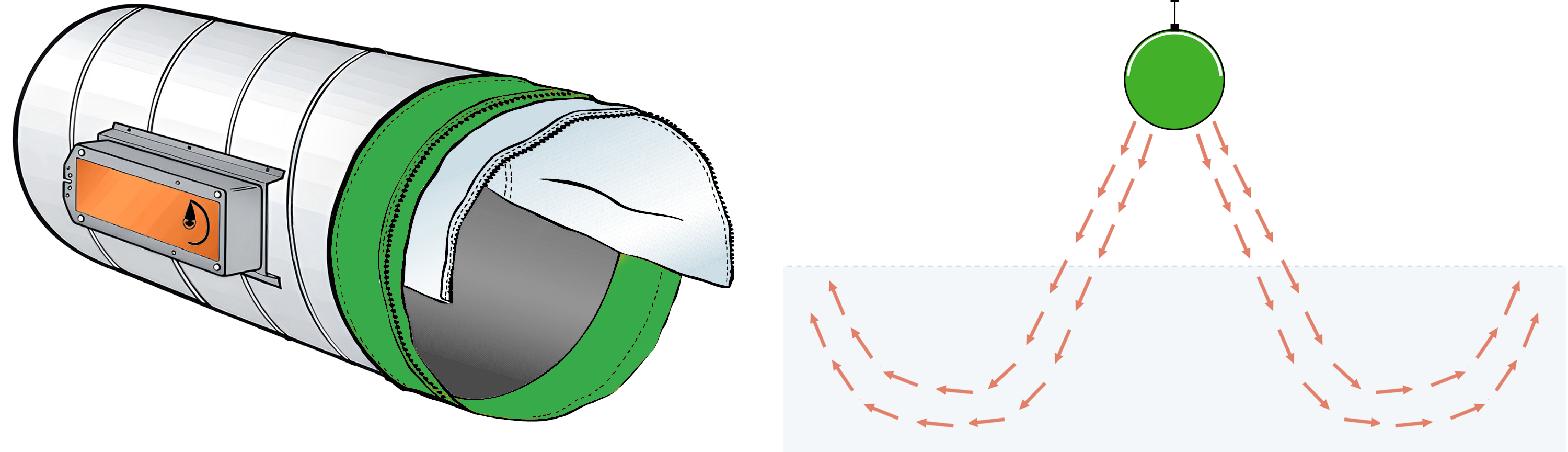
Cooling mode
Cold air is distributed exclusively through the upper half. The lower part with perforation remains covered by the membrane.
The airflow takes advantage of the natural downward movement of denser cold air. As a result, the cold air gradually spreads into the space, naturally displacing the warmer air from the lower zone of the room.
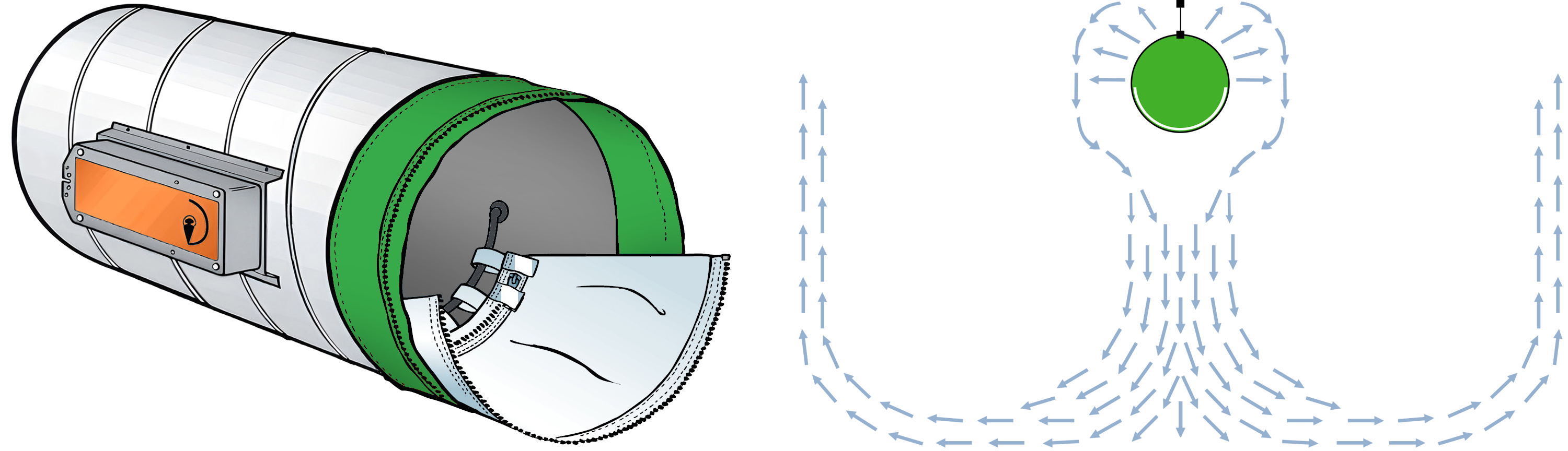
Heating mode
Warm air is supplied exclusively through the lower perforated surface of the duct, while the upper part is covered by an insulating membrane that prevents air from escaping upward.
Thanks to the perforation, the warm air exits the outlet at a higher velocity, allowing it to penetrate the occupied zone without immediately rising.
How to install the membrane?
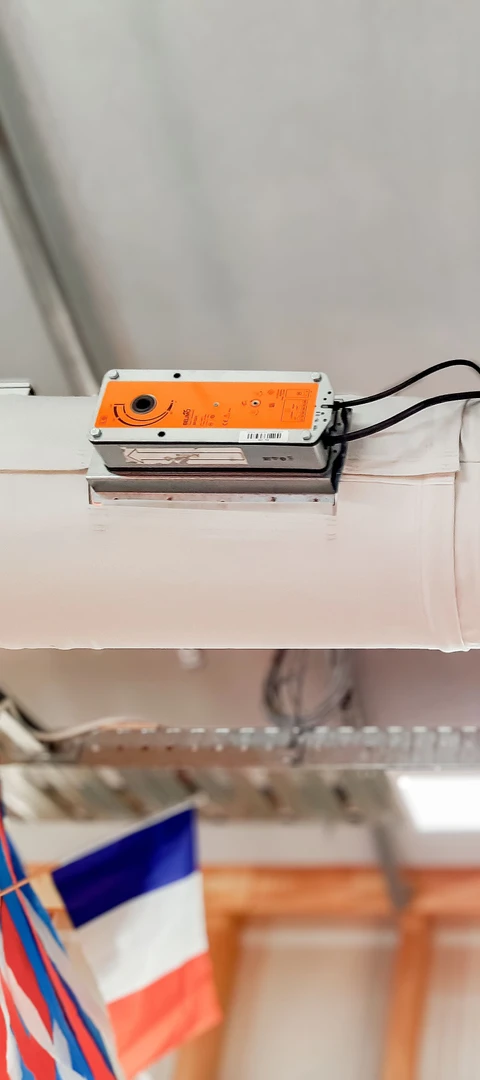
The membrane system shipment includes a textile duct with an integrated airtight layer, a short metal inlet duct with a motor, and mounting accessories for suspending the duct.
Installation steps:
- Attach the inlet metal duct with the motor to the air supply.
- The standard position of the positioning motor is on the right-hand side in the direction of airflow.
- When the membrane is not connected to power, the motor indicator should point to the heating position, i.e. upwards.
- The textile straps on the airtight layer are wrapped around and fastened with a zipper to the positioning bracket inside the metal duct.
- Attach the duct to the initial position, which is already fixed to the metal duct.
- Ensure that the membrane is properly aligned and that the seam separating the heating and cooling halves (typically containing the perforation) is exactly centered at the 3 and 9 o’clock
positions.
- Ensure that the membrane is properly aligned and that the seam separating the heating and cooling halves (typically containing the perforation) is exactly centered at the 3 and 9 o’clock
- Attach the sections of the duct and membrane using zippers, ensuring they connect seamlessly.
Get the Product Overview for free
Detailed information in one place.
Download the product overview that summarizes everything that is important about membrane systems: operating principle, installation and detailed technical specifications of the positioning motor.
The overview will facilitate designing process, installation and communication with the investor.
Get in touch with us
Your next successful project starts right now.Our experts are ready to help you bring it to life.
With us, you can be sure of a response to your request within 24 hours.